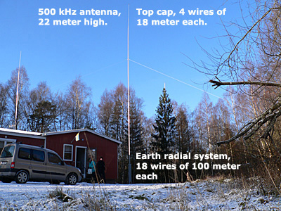
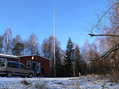
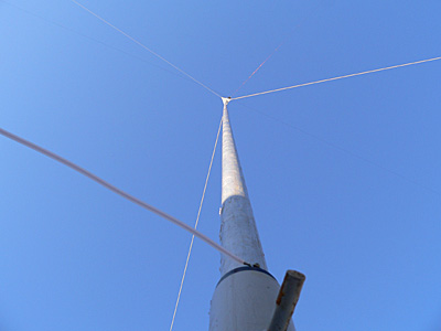
Info about our 500 kHz installation We got our licence in august 2008, and when the paper arrived we got in big hurry to put something "on the air" directly. A new vertical antenna
was also built, about 22 meter high vertical pipe, with 4 top cap wires at
a total length of 18 meter. The earth radials consists of 18 wires spread
out like a star, and each of thoose wires are 100 meter,
this is in duty since 2008-11-22, a cold november day in Sweden, perfect for antenna work... ;-) Radiated power
is about 3 watts erp. Best 73's from the crew at SK6RUD - Radio Rud
|
|
 |
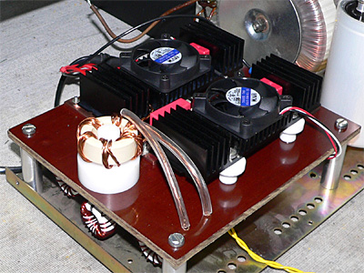 |
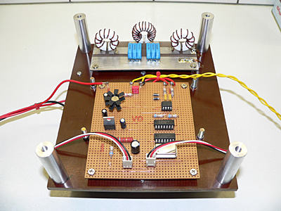
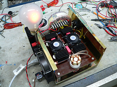
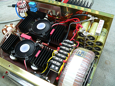
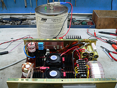
| Bottom side with logic board and low pass filter. | Top side, 2 POWER MOSFET, cooling fans and transformer. |
 |
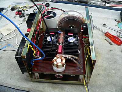 |
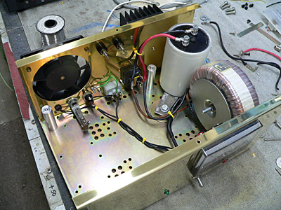
| Box with power supply, cooling fan, without transmitter. | Box with power supply, cooling fan, and the transmitter. |
 |
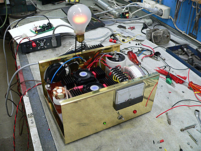 |
| Some final tests of the transmitter, the light bulb goes on! | Some final tests of the transmitter, the light bulb goes on! |
 |
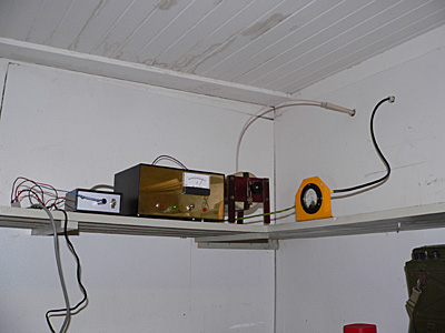 |
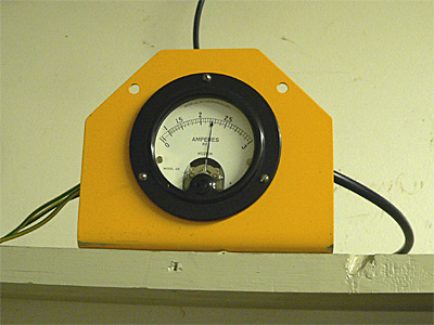
| RF Ampere meter connected to our earth radials. | Photo of the installation, keyer, transmitter and variometer. |
 |
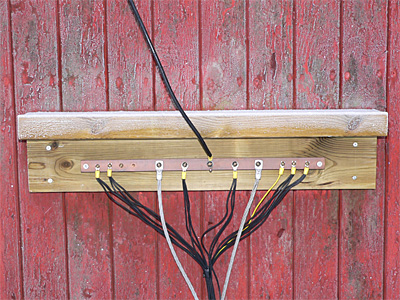 |
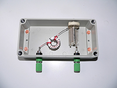
| This is what we use to get thoose radio waves in the air. | Center connection point of the earth radial system. |
 |
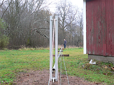 |
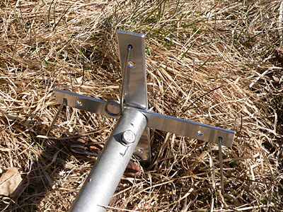
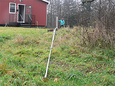
| Top end of the new vertical with flexible holdings for cap. wires. | Vertical antenna, not yet erected. SA6AMV 22 meters away. |
 |
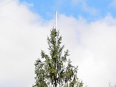 |
| Vertical antenna with commander in chief SM6YJG. | One of the 4 top cap wires 20 meters up in a tree. |
 |
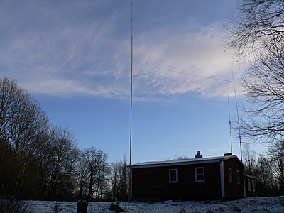 |
| New vertical antenna On The Air 2008-11-22 | New vertical antenna On The Air 2008-11-22 |
 |
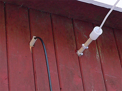 |
| View from bottom of the vertical... | Two holes in the wall, one for earth wires, one for the antenna. |
 |
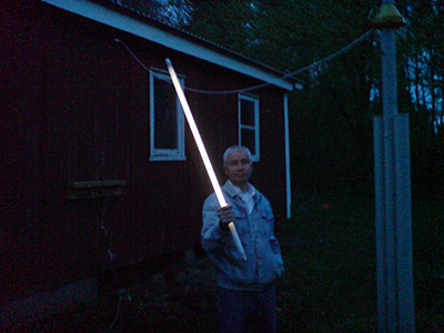 |
| Tx with new passband filter and more uF filter condensators. | Not Darth Vader but SM6BGP with a fluorescent near antenna. |
 |
 |
| Tx on workbench for final tests with connected dummyload. | Wave trap for 3500 kHz now connected at beacon installation. |
 |
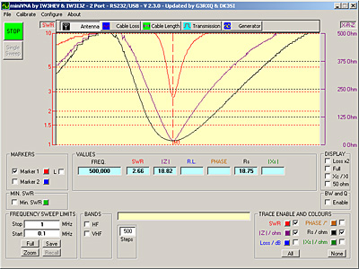 |
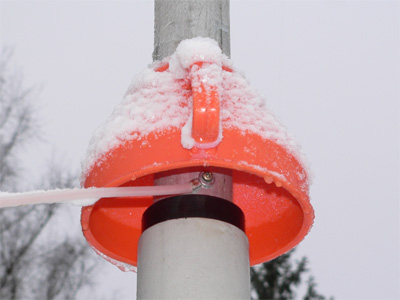
| Improvment, a modified gasoline funnel keeps the isolator dry! | Some pictures from todays antenna measurements... ;-)) |
 |
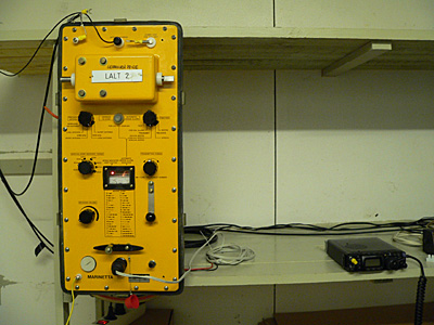 |
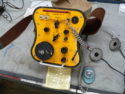
| Photo of the first try, Skanti Marinetta life boat transmitter. | Photo of the second try, also Skanti life boat transmitter. |